


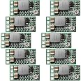
Weewooday 10 Pieces 5v Regulator Module Mini Voltage Reducer DC 4.5-24V 12V 24V to 5V 3A Volt Buck Converter Power Supply Transformer Module
Details
- BrandWeewooday
- Connectivity TechnologyProprietary
- Compatible Devices[INFERRED] a
- Compatible Phone Models[INFERRED] a
- Included Components10 x Mini 5v
- Input Voltage24 Volts
Description
🔌 Power Up Your Projects with Precision!
- 🔋 HIGH EFFICIENCY - Achieve up to 97.5% conversion efficiency for optimal performance.
- 🔌 EASY INTEGRATION - Connect directly to car batteries without the need for additional switches.
- 🌡️ LOW HEAT GENERATION - Designed with high current shielding to minimize heat and maximize longevity.
- 🛡️ RELIABLE PROTECTION - Built-in short circuit protection ensures safety during operation.
- 🔄 VERSATILE VOLTAGE OPTIONS - Choose from fixed outputs of 1.8V, 2.5V, 3.3V, 5V, 9V, and 12V.
The Weewooday 10 Pieces 5V Regulator Module is a high-performance voltage reducer designed for versatility and efficiency. With an input range of DC 4.5-24V and adjustable output options, this module is perfect for various applications. Its compact design and high current capabilities make it an essential tool for any tech-savvy professional.
Specifications
| Energy Specifications Standard | Ma |
| Number of Items | 10 |
| Unit Count | 1.0 count |
| Enclosure Material | Electronic components and materials |
| Current Rating | 3 Amps |
| Power Plug Type | No Plug |
| Power Source | Corded Electric |
| Portable | No |
| Wattage | 693 Watts |
| Amperage | 3 Amps |
| Frequency Range | 500 KHz, NO |
| Mount Type | Board Mount |
| Output Current | 3 Amps |
| Input Voltage | 24 Volts |
| Main Power Connector Type | 2 pin |
| Additional Features | Short Circuit Protection |
Reviews
D**D
Awesome little buck converters
There are a few bad reviews on this item, but I have purchased this buck converter several times and I have been happy with every single one of them. Perhaps the documentation is insufficient or missing, but if you're buying one of them you probably at least THINK you know what you're doing, and when the negative reviewers connected it wrong and it short circuited, they decided to blame the device for their misuse.Connections:On one end of the chip there are 4 solder pads that are labeled VO+, GND, IN+, and EN.VO+ = the positive output pin (stepped down to whatever you select)IN+ = the positive input pin (acceptable range between 4.5V and 24V)GND = shared/common ground for your input and output (e.g. BOTH input and output negative grounds are connected to this one, single pin).EN = enable port (e.g. used to turn power on or off like a relay)Unless you plan to use a GPIO pin (Arduino, RPi, etc.) to signal the enable port (e.g. to turn power on/off), just ignore the EN pad. If you do want to power it on and off, connect a GPIO pin to the EN pin and set the GPIO to HIGH to STOP power flow through the chip and LOW to turn it ON. I typically don't use the EN port for my projects, but it's a nice feature. Note: If you wire the EN pin as a ground for your voltage in (which is likely what the bad reviewers did), it will short circuit. Don't do that and then complain that the chips are bad - they're not; you just wired it incorrectly. The EN port is NOT a ground.Voltage selection:The trickier part is voltage selection. Remember, this is ONLY a voltage reducer. If you feed it 4.5V, you can't get 12V out of it. Your desired output voltage must be LOWER than your input voltage. Also, BY DEFAULT, the potentiometer on the top of the chip is what is used to adjust the voltage. If you prefer to use the solder pads on the back to step down to a pre-defined voltage, you have to cut the connection on the ADJ jumper pad that is connected on the printed circuit board (the connection you need to cut is under the green shielding). Cutting this connection is probably the most difficult thing to do on the device. An X-Acto knife works well for it, but it takes some effort to cut all the way through the connection without cutting your finger (ask me how I know). For the sake of safety, I typically adjust the potentiometer using a power supply for my power input and a voltmeter to check the voltage output.Depending on the project, once I have everything soldered and adjusted, I typically use a piece of adhesive-filled heat shrink tubing to cover the entire chip. This will:1. lock in the potentiometer setting and2. seal everything up nicely to keep it waterproof.
J**W
10 of 20 burned out more or less instantly
I bought 80 of these (8 packs of 10) for a project where I need 60 of them. Of the first five, the first three cooked within seconds of being energized for testing. Maybe some of that was my fault, like I touched something with a probe or something. I'll be the first to blame user error.Then a few more burned out as I was being VERY careful with them not to short anything by mistake. Some I had set to 3.3V got really hot. Multimeter had a tough time measuring the voltage on some of them, but if I just held the probes on the output for long enough it'd eventually read 3.3v consistently. 5V seemed to do a little better.I assembled a device with five of these - four at 5 Volts and one at 3.3 and carefully brought up the supply voltage. No loads attached at this point, just verifying they were supplying safe voltages. Current draw was pretty acceptable at 60mA for all five.I couldn't quite force myself to energize this unit with a full 12V under the actual load of use - about 1A each of the 5V and 300mA on the 3.3V. Something about it gave me the creeps.So, I very carefully assemble another setup with four 5s and a 3.3. I'm especially careful to solder everything independently and make sure all is very clean and the process is clearly thought out and protects the converters from excessive heat or unwelcome touching. I connect the all the loads. I hook it up to a different 12V power supply. Flames immediately flare out of three of the five volt converters. One 5V appears not to have burned out, and the one set to 3.3V also seems ok visually. You can see exactly which component died in all cases.I don't dare to try any more of these, lest they destroy the components they're supposed to be powering.I'm still sitting on 60 of these things, so I figure - before I push go on this one-star review, let's do one more test. I hook it up and run it up to 12V. It seems to want to spit out a nice 5V. On the oscilloscope, the output is good. But it randomly gets really hot, and my whole workshop smells like burned out electronics. I just don't trust them anymore. I'm sitting right around a 50% failure rate with the legitimate potential to start a fire.This is by no means a sterile laboratory environment, and I bought an extra 20 because I figured I'd make a mistake here or there. But I'm not THIS incompetent. I'm not going to attempt to use these converters further. Bought 15 chunkier 5V 10A regulators instead and will share the load from one regulator instead of relying on four smaller ones. I'll just hook up an LDO regulator to pipe down to 3.3V from the 5V rail.I doubt the 25% of reviews with one star would have deterred me from making the purchase. I love a good adventure, after all. This is one of those rare times where whatever I just bought is utterly unfit for a task for which the product description clearly said it would be well suited. If you're smarter than me, you'll avoid these. Or maybe your extra wit will enable you to use them successfully. Good luck!
A**D
Great regulator
Really compact and small enough to fit in a very tight space. Works perfectly
B**C
Handy little device, with design limitations
This switchmode regulator module was quite useful in replacing a linear voltage regulator to reduce the current draw of my design, but it is not a "drop in" replacement. I had to make several changes in my design (due to ripple effects) and I had to modify the module to get the output voltage accuracy I required. My design is battery powered, 12V nominal. Much of my design runs straight off this 12V supply, but some circuits in the design require 5.00V +/-10mV @ 100-150mA. For purposes of testing, I used a 40Ω resistor to load the output of the switchmode module at 125mA.I have tested only two of the 10 modules I received, but both worked well. No functional problems. I first tried to use the adjustment pot to set the voltage accuracy I required. No joy. The pot is very sensitive. The slightest movement of the slider produced at least a 50mV change in the output voltage. I decided I had to use the fixed resistors.However, during this testing, I noted two problems. The photo sows the voltage ripple and the switching frequency of the switchmode regulator. The vertical scale is set to 20mV/div and the horizontal scale is set to 2us/div. The ripple is 60mVpp and the switching period is 6.4us, for a frequency of 156kHz, not the 500kHz claimed by the seller. During this testing, I briefly turned the output voltage up to 10V, which increased the output current to 250mA. The switcmmode control chip got quite hot. I did not measure the temperature. However, if your design will draw 500mA or more, you really should investigate this temperature rise. I truly would be surprised if this module can deliver 1.5A of output current without special measures for cooling, as claimed by the seller.My next step was to cut out the trim pot and used the 5V fixed resistor. The first module delivered 5.077V. That is 1.5% accuracy, which really isn't bad. The second module delivered 5.105V. I realized that I was unlikely to find a module that gave me the 5.00V +/-10mV that I required. So I unsoldered the fixed resistor for a 1.8V output (on the first module) and replaced it with a 2MΩ resistor (both 0603 size, which are fun to work with). I then also bridged the pads for that resistor, which put it in parallel with the 39kΩ resistor for a 5V output. The output voltage dropped to 4.996V - well within my requirement.The 60mVpp ripple caused severe problems for a voltage comparator circuit. This circuit drew only 1mA, so I added a simple RC filter (10Ω, 10uF) in the 5V supply for this circuit, and adjusted the resistor values in the reference voltage divider to account for the 10mV voltage drop. Problem solved.The 27uF (?) input capacitor on the switchmode regulator still allowed a significant ripple current in the 12V supply line. Perhaps because of resistance in the battery, this created ripple on the 12V supply for the entire design, causing problems. I added a 47uH inductor in the 12V supply to the switchmode regulator, which solved that problem.So, I am glad this switchmode regulator module was available, and using it it did extend my battery life by about an hour and a half. But using this regulator in place of a linear regulator brings its own set of problems with it. Design with care.
C**Z
My go-to regulator
I've used these quite a bit in the past and they are great. I have not had much luck with cutting the traces on the back to lock in specific voltages so I just use the on-board pot and adjust the voltage down and then if needed you could use flexible glue like E6000 to lock the pot in place. I've not found any issues with voltage changing though. These are very versatile and I'll continue to buy more.
Common Questions
Trustpilot
2 weeks ago
2 weeks ago
Get the App
